Description
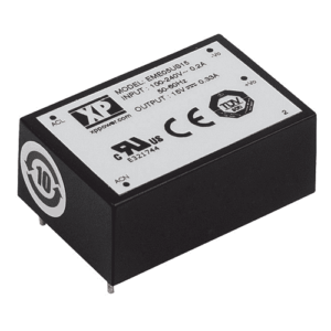
ECF40 Series AC-DC Power Supplies 40 Watts
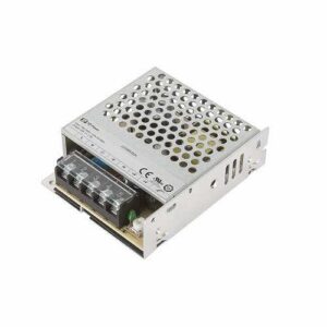
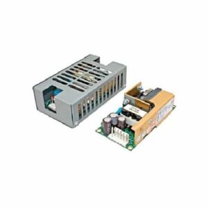
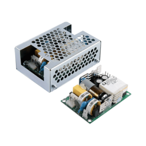
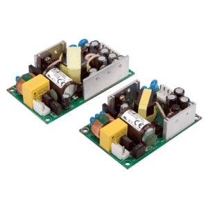
Open frame – Low Profile AC/DC Power Supply
The ECF40 series is designed to minimize the no load power consumption and maximize efficiency to facilitate equipment design to meet the latest environmental legislation. Approved for medical and ITE applications in either Class I or Class II installations, this range of single output AC-DC power supplies are packaged in a low profile 1.1” height with a foot print of just 1.5” by 3”. The ECF40 provides up to 40W convection-cooled over the full 90-264 VAC input range, and operates down to 80 VAC with minimal de-rating. The power supply features two AC line fuses and low leakage currents required by medical applications. The low profile, low noise and safety approvals covering ITE and medical standards allows the versatile ECF40 series to be used in a wide range of applications.
Service life
The estimated service life of the ECF40 is determined by the cooling arrangements and load conditions experienced in the end application. Due to the uncertain nature of the end application this estimated service life is based on the actual measured temperature of key capacitors within the product when installed by the end application.