| Input | | | | | |
| Characteristic | Minimum | Typical | Maximum | Units | Notes & Conditions |
| Input Voltage Range | 9
18 | | 36
75 | VDC
VDC | 24 V nominal
48 V nominal |
| Input Current | | | | | See Models and Ratings table |
| Inrush Current | | | | A | |
| Input Filter | Pi type | | | | |
| Undervoltage Lockout | On at >9 V. Off <7.5 V
On at >18 V. Off <16.0 V | | | | 24 V models
48 V models |
| Input Surge | | | 50
100 | VDC
VDC | 24 V models for 100 ms
48 V models for 100 ms |
| Remote On/Off | On: Logic High (3.5-12 V) or open circuit
Off: Logic Low (<1.2 V) or short pin 1 to pin 2 | | | | |
| Output | | | | | |
| Characteristic | Minimum | Typical | Maximum | Units | Notes & Conditions |
| Output Voltage | 5.1 | | 48 | V | See Models and Ratings table |
| Initial Set Accuracy | | ±1 | ±2 | % | |
| Minimum Load | 0 | | | A | No minimum load required |
| Start Up Delay | | 50 | | ms | |
| Line Regulation | | ±0.5 | | % | |
| Load Regulation | | 1 | | % | 0 – 10% load |
| Transient Response | | | 5 | % deviation | Recovery to within 1% in <250 μs for a 50% load change
at 0.25 A/μs rate |
| Ripple & Noise | | | 100
150
200 | mV pk-pk | 5.1 V model, 20 MHz bandwidth
12 V & 48 V models, 20 MHz bandwidth
48 V model, 20 MHz bandwidth |
| Short Circuit Protection | | | | | Trip & Restart (hiccup mode), auto recovery |
| Overload Protection | | 150 | | % | Trip & Restart (hiccup mode) |
| Overvoltage Protection | | 120 | | % | Zener diode clamp |
| Temperature Coefficient | | | 0.02 | %/ °C | |
| General | | | | | |
| Characteristic | Minimum | Typical | Maximum | Units | Notes & Conditions |
| Efficiency | | 90 | | % | See Models and Ratings table |
| Isolation | 2500 | | | VDC | For 60 s |
| Isolation Resistance | 1000 | | | MΩ | At 500 VDC |
| Input to Output Capacitance | | | 2200 | pF | |
| Switching Frequency | | 285 | | kHz | |
| Power Density | | | 2.7 | W/in3 | |
| Mean Time Between Failure | 750 | | | kHrs | MIL-HDBK-217F, +25°C GB |
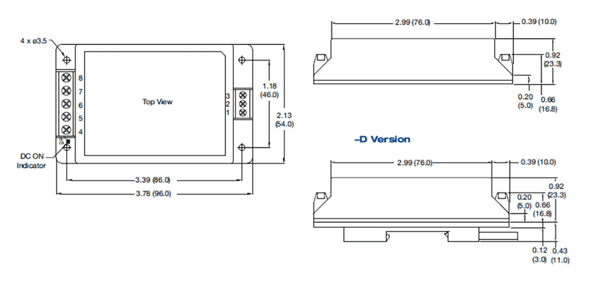
| Weight | | 0.214 (107) | | lb (g) | |
| Environmental | | | | | |
| Characteristic | Minimum | Typical | Maximum | Units | Notes & Conditions |
| Operating Temperature | -40 | | +85 | °C | See derating curve |
| Storage Temperature | -50 | | +125 | °C | |
| Case Temperature | | | 95 | °C | |
Thermal Impendance
(Case to Ambient) | 3.9
3.9
3.1
2.5 | | | °C/W | Natural convection
100 LFM
200 LFM
400 LFM |
| Humidity | 5 | | 95 | %RH | Non-condensing |
| Cooling | | | | | Natural convection |
| Shock | ±3 shocks in each plane, total 18 shocks of 30 g : 11 ms halfsine. Conforms to EN60068-2-27 & EN60068-2-47 |
| Vibration | 10-500 Hz at 2 g sweep and endurance at resonance in all 3 planes. Conforms to EN60068-2-6 |
| EMC: Emissions | | | | | |
| Phenomenon | Standard | Test Level | | | Notes & Conditions |
| Conducted | EN55022 | Level A | | | With no external components |
| Radiated | EN55022 | Level A | | | See application notes |
| EMC: Immunity | | | | | |
| Phenomenon | Standard | Test Level | Criteria | | Notes & Conditions |
| Immunity | EN55024 | | | | |
| ESD Immunity | EN61000-4-2 | ±4 kV Contact, ±8 kV Air | A | | |
| Radiated Immunity | EN61000-4-3 | 10 V/m | A | | |
| EFT/Burst | EN61000-4-4 | 3 | A | | |
| Surges | EN61000-4-5 | 3 | A | | |
| Conducted Immunity | EN61000-4-6 | 10 Vm | A | | |
| Magnetic Fields | EN61000-4-8 | 30 A/m | A | | |